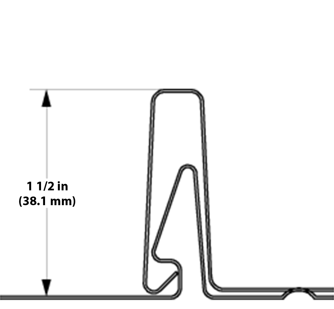
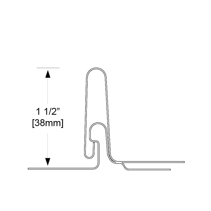
The S-5-N 1.5 (“N” stands for nail strip) is a non-penetrating, standing seam metal roof (SSMR) clamp.
The N 1.5 is the right choice for 1.5″ (38 mm) nail strips, such as: Bridger Steel 1.5” Tru Snap, Schlebach 1.5” NailStrip, Sheet Metal Supply NS 1.5”, Sheffield Metals SMI 1.5” and roofing types with similar profiles.
(For nail strip profiles with 1” seam height, see “S-5-N.”)
Minis Available
The N 1.5 Mini clamp is a more economical solution for lighter-duty attachments where Herculean holding strength is not required.
All standard and Mini clamps undergo rigorous load testing. Negative load normal-to-seam testing (pull-up) is performed on all Mini clamps, and parallel-to-seam testing (drag load) is performed on all standard clamps.
Choose the N 1.5 to mount to nail flange metal roof profiles with a seam base dimension ≤ .50” (12.7 mm). (For nail strip profiles outside this dimension, please see the “S-5-NH 1.5”).
Be sure to check out the many other features on the clamp overview page.
Nail Strip Standing Seam
N 1.5 Metal Roof Seam
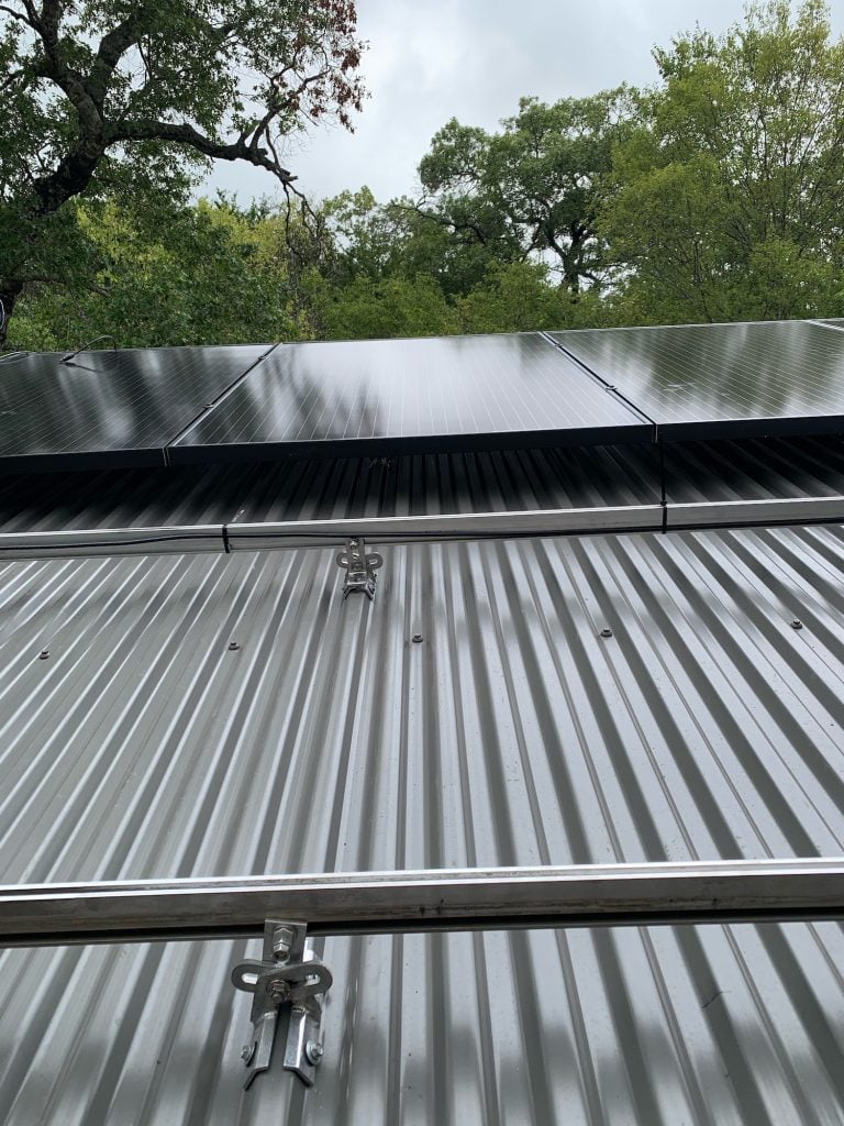
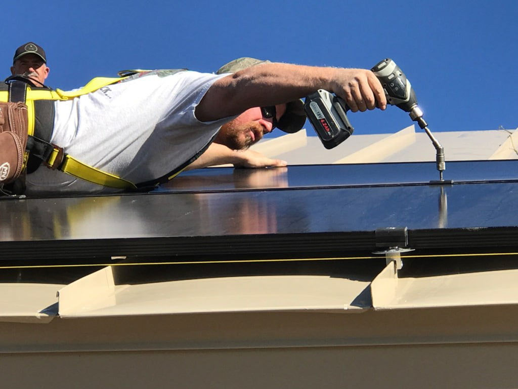
Installation is as simple as placing the clamp on the seam and tightening the round point Torx Drive (T30) setscrews to the specified tension. Then, affix ancillary items using the bolt (provided with standard N 1.5 clamp; sold separately for the N 1.5 Mini).
Special design of the S-5-N 1.5’s angled wall and nose engages triangle type rib profiles during installation.
*See more detailed installation instructions in the PDF download below.
*S-5! clamps may be moved in the event of initial misplacement. However, due to the ensuing oxidation process which acts as a natural thread lock, we can express no opinion to the performance of a clamp once it has been removed and reinstalled or the ability to remove the clamp after this process has occurred.
Submit your information by clicking the form below, and we’ll get back to you as soon as possible.
S-5! offers 3 specific clamp options for nail-flange.
The S-5-N (and Mini) (also with an insert) are designed for applications on popular 1″ (seam height) nail strip metal roof profiles: Taylor Metals’ Easy Lock™, ASC Building Products’ Skyline Roofing®, McElroy Metals’ Meridian, and New Tech Machinery’s FF100, and roofing types with similar profiles.
The S-5-N 1.5 (and Mini) are designed for most 1.5″ (seam height) nail strip metal roof profiles such as: Bridger Steel 1.5” Tru Snap, Schlebach 1.5” NailStrip, Sheet Metal Supply NS 1.5”, Sheffield Metals SMI 1.5” and roofing types with similar profiles.
The S-5 NH 1.5 (and Mini) were designed to fit wider profiles that the S-5-N 1.5 will not fit.
These clamps feature a hinged insert for limited wider nail strip profiles to prevent damage to the seam area on these wider seam profiles and are ideal for VicWest “Prestige” and similarly-dimensioned profiles. It is designed specifically for 1-1/2” (seam height) nail-flange profiles having a horizontal base-of-seam dimension (> 0.475” and < 0.800”).
Our standard test procedures are to test the Mini (one setscrew) clamps with negative load normal to seam and standard (two setscrew) clamps with load parallel to seam. We have performed numerous parallel-to-seam datum tests on Mini clamps and concluded the Mini clamp is capable of (conservatively) obtaining at least ½ the strength of the standard clamps. In fact, the majority of the datum testing indicates the strength of a Mini is closer to 2/3 the strength of a standard clamp.
Should the load application pulling load parallel to seam be critical to your application, we suggest using the standard (two setscrew) design.
The following suggestions assume a determination has been made that the roof to which the S-5! clamps will be attached is structurally adequate. Any loads imposed on the S-5! clamps will be transferred to the panels. Panel seams must have sufficient flexural strength to carry these loads. Panels must also be adequately attached to the building structure, and the structure must be sufficient to carry these loads. The makers of S-5! clamps make no representations with respect to these variables. It is the responsibility of the user to verify this information or seek assistance from a qualified design professional, if necessary.
The key to frequency and spacing of attachment points for PV is to distribute loads to the metal standing seam panels in a manner consistent with the intended distribution of loads from the roof panels into the building structure. With very few exceptions, the attachment of a single S-5! clamp (even the “Mini”) to the seam will be stronger than a single point of attachment of the seam to the building structure. Hence, the “weak link” is not the S-5! clamp, but the attachment clips that hold the metal panels to the building structure or the beam strength of the roof panel seam itself.
The most conservative approach to the spacing/frequency of PV attachment to the roof is to determine the spacing/frequency of the roof’s attachment to the building structure; then duplicate it at minimum. Determining panel attachment spacing in one axis is very simple: A standing seam panels’ attachment will be made using concealed hold-down clips within the seam area of the panel. So, in that axis, the clip spacing is the same as the seam spacing. The location of the clips along the seam (in the other axis) can be determined by a) consultation with the roof system manufacturer or installer, b) checking from the underside or, c) close examination from the topside along the seam. There will usually be a slight, but detectable, deformation of the seam at the clip location visible from the roof’s topside. Many standing seam roofing systems are installed on “pre-engineered steel” buildings. The attachment spacing in that industry is typically 5’-0” and is readily apparent by inspecting the structural purlins to which the panel clips are attached from the roof underside (interior of the building).
If the panel clips are spaced, for instance, 5′-0″ on center along the seam, then use the 5′-0″ dimension as a maximum spacing for the S-5! clamps. (S-5! clamps may also be spaced at closer centers, but not wider.) When modules are direct-attached (without racking) in landscape orientation, this spacing dimension is dictated by the smallest dimension of the PV frame. Using the roof panel clip spacing as a maximum spacing template for S-5! clamps is a sound practice whether the PV modules are attached directly to S-5! or to a racking system, which is in turn, attached to the S-5! (and panel seams). To evenly distribute loads, it is also necessary for each seam to be involved in the finished assembly. Thus, every time a seam is traversed, it should be attached. Such an attachment scheme should evenly distribute wind loads into the building structure through the panels and their attachment, as intended in the original roof construction assembly.
Please note, these are only suggestions. Wind dynamics are complex, and S-5! advises review by a qualified licensed professional who understands wind effects and metal roof design and construction.
The answer to this question varies with the load direction, the seam profile, the roof material and the clamp model.
These variables result with a wide range of holding capacities from ±300 lbs (235 kg) to ±4,000 lbs (1800 kg). This is why for critical applications it is important to correctly identify the roof panel, seam type, gauge, etc along with the recommended seam clamp for the specific roof. [ link-- Clamp-to-seam tool] When used on some “applied cap” architectural type seam styles, S-5! may yield low load-to-failure results as compared with integrated seam profiles. Always check our load table to verify the correct allowable holding strength on your specific roof type. Read more.