The following suggestions assume a determination has been made that the roof to which the S-5! clamps will be attached is structurally adequate. Any loads imposed on the S-5! clamps will be transferred to the panels. Panel seams must have sufficient flexural strength to carry these loads. Panels must also be adequately attached to the building structure, and the structure must be sufficient to carry these loads. The makers of S-5! clamps make no representations with respect to these variables. It is the responsibility of the user to verify this information or seek assistance from a qualified design professional, if necessary.
The key to frequency and spacing of attachment points for PV is to distribute loads to the metal standing seam panels in a manner consistent with the intended distribution of loads from the roof panels into the building structure. With very few exceptions, the attachment of a single S-5! clamp (even the “Mini”) to the seam will be stronger than a single point of attachment of the seam to the building structure. Hence, the “weak link” is not the S-5! clamp, but the attachment clips that hold the metal panels to the building structure or the beam strength of the roof panel seam itself.
The most conservative approach to the spacing/frequency of PV attachment to the roof is to determine the spacing/frequency of the roof’s attachment to the building structure; then duplicate it at minimum. Determining panel attachment spacing in one axis is very simple: A standing seam panels’ attachment will be made using concealed hold-down clips within the seam area of the panel. So, in that axis, the clip spacing is the same as the seam spacing. The location of the clips along the seam (in the other axis) can be determined by a) consultation with the roof system manufacturer or installer, b) checking from the underside or, c) close examination from the topside along the seam. There will usually be a slight, but detectable, deformation of the seam at the clip location visible from the roof’s topside. Many standing seam roofing systems are installed on “pre-engineered steel” buildings. The attachment spacing in that industry is typically 5’-0” and is readily apparent by inspecting the structural purlins to which the panel clips are attached from the roof underside (interior of the building).
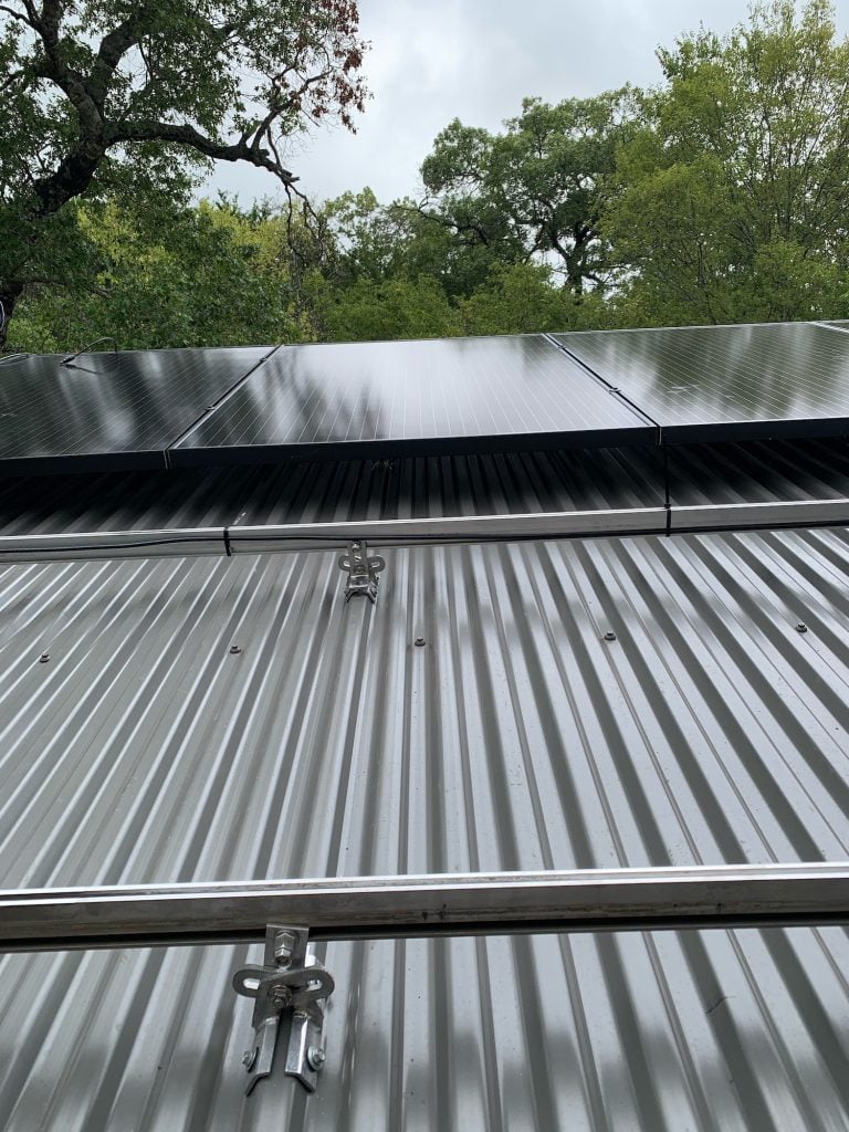
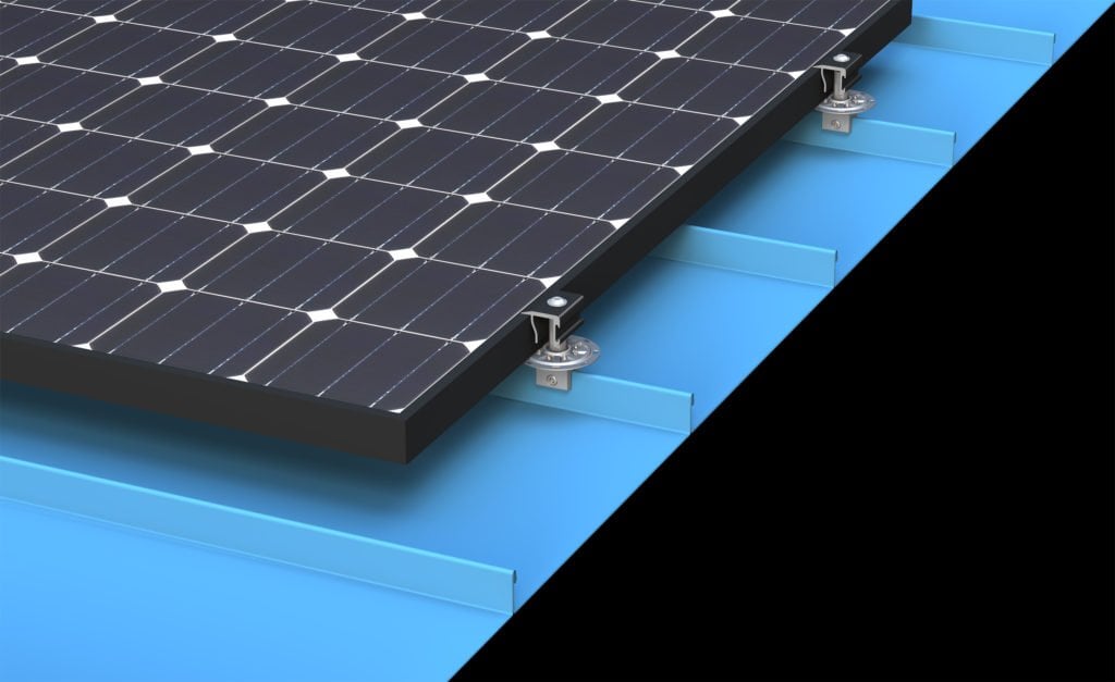
If the panel clips are spaced, for instance, 5′-0″ on center along the seam, then use the 5′-0″ dimension as a maximum spacing for the S-5! clamps. (S-5! clamps may also be spaced at closer centers, but not wider.) When modules are direct-attached (without racking) in landscape orientation, this spacing dimension is dictated by the smallest dimension of the PV frame. Using the roof panel clip spacing as a maximum spacing template for S-5! clamps is a sound practice whether the PV modules are attached directly to S-5! or to a racking system, which is in turn, attached to the S-5! (and panel seams). To evenly distribute loads, it is also necessary for each seam to be involved in the finished assembly. Thus, every time a seam is traversed, it should be attached. Such an attachment scheme should evenly distribute wind loads into the building structure through the panels and their attachment, as intended in the original roof construction assembly.
Please note, these are only suggestions. Wind dynamics are complex, and S-5! advises review by a qualified licensed professional who understands wind effects and metal roof design and construction.